In this practice, we will see how to simulate our project created with the Unity Software and then link it with the HMI software Vijeo Designer and the SCADA Vijeo Citect.
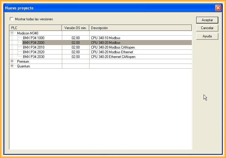
1.- The first step will be to create a new project, selecting a model from the available range, depending on the version of the installed software. For this practice, you can see the one I have selected.
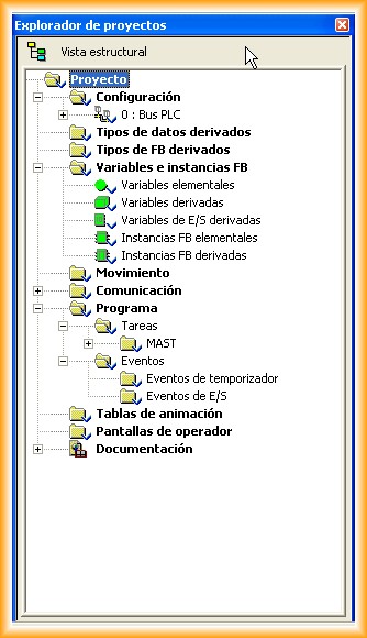
Here you can see the structural view of our project. The next step will be the hardware configuration.
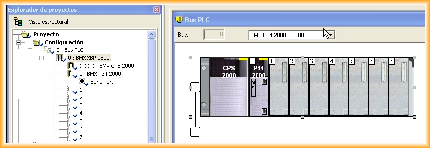
By double-clicking on the PLC Bus, the following image will open. Now, depending on the cards we have, we will insert them into their corresponding slot. For the simulation, I will insert an input card, output card, and the most important for the simulation, an Ethernet card.
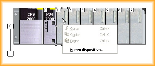
We select the corresponding Slot and with the right button, New device... a pop-up window will open to select the type of module to insert. In slots 1 and 2, we insert the cards mentioned above.
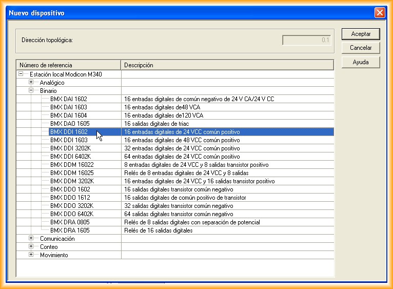
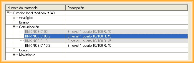
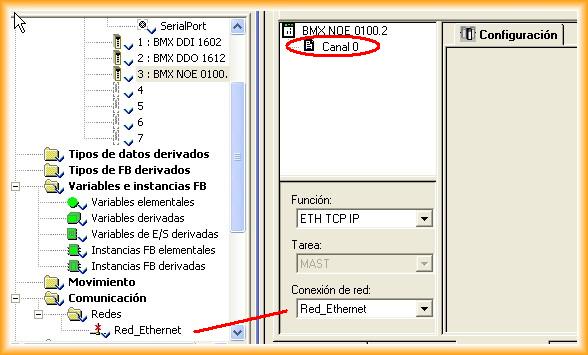
In slot number 3, we insert the network card that we will configure next.
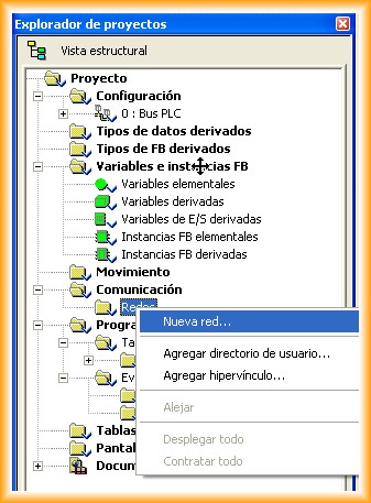
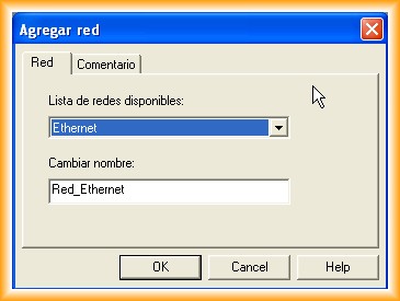
The next step is to configure a new network. Since we have a network card, we go to communication -> Networks and add a new network. A pop-up window will open to select the type of network and its name. The type of network will depend on the cards we have available. For this example, our network will be called Ethernet_Network.
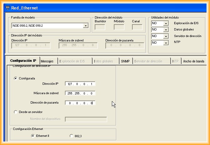
The next step is to configure our card, assign it to a network, and specify an IP address. Since this practice is oriented towards simulation, the IP address should be specified as 127.0.0.1. This address is a reserved address that is the same as localhost.
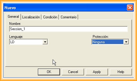
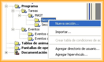
So far, we have completed the configuration of our hardware! Now we just need some lines of programming code and to test its functionality. To create a new section, we follow the steps according to the image and add it, specifying a name and programming language.
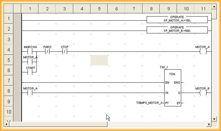
We create some contacts, some data movement, and a timer for later visualization on the HMI screen. In short, let your imagination run wild, and we compile from time to time to ensure we haven't made any mistakes.

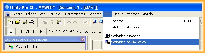
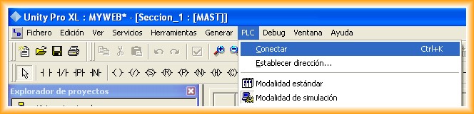
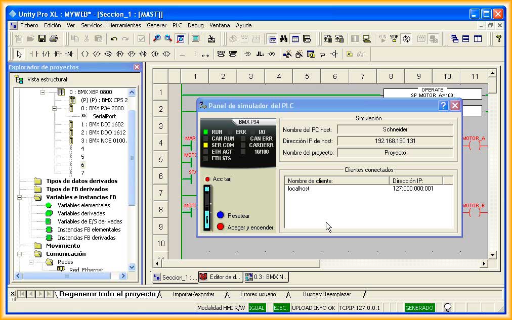
The steps to perform the simulation are as follows; each image is a step to follow, a picture is worth a thousand words...
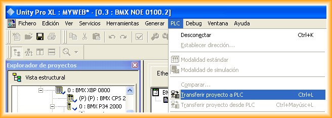
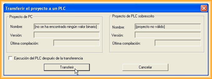
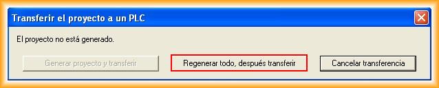
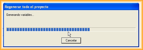
With the described steps, we have already transferred our project to our PLC, and its appearance is as follows. Now we just need to press the RUN symbol, and our program will execute.
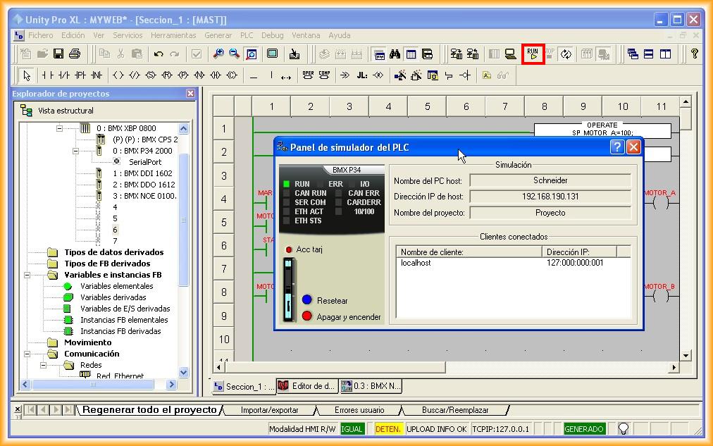
Once in RUN, our program is processed cyclically. To interact, we can either force values or create an animation table.
To return to the editor, we must follow the steps in reverse: put our PLC in STOP -> Disconnect -> and return to Standard Mode.
Update: May 18, 2013. Video of the detailed description above in conjunction with Vijeo Designer. I recommend changing the video quality to 720p.