Building on the introduction I made in the previous practice, The simulation of a Modbus RTU Network, today we are going to configure the Siemens S7-200 to act as a Slave in a Modbus Network, redundancy intended.
To carry out this practice we will need the Modbus libraries for Microwin, the software used to program this PLC, and we will use Modbus Poll to check the operation.
We create a new project in Microwin and we will only use the two functions that we need.
MBUS_INIT, this function is used to initialize, activate or deactivate communication and will only be executed depending on the needs of our program, in this example it will only be executed in the first scan cycle and the function MBUS_SLAVE will be executed if no error occurred during initialization or activation, as I use the Done bit to execute it, it is an output to be able to check it directly on the PLC, as I cannot be online at the same time.
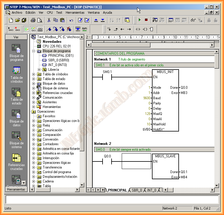
Mode = 1 Modbus Communication
Addr = Slave Address
Baud = Communication Speed, as established in the Network
Parity = Parity 0, even or odd
Delay = Default 0
MaxIQ = 128 Access to all Inputs/Outputs, 0 Restriction to them
MaxAI = Access to Analog Inputs/Outputs, depending on the type of CPU it varies. 0 restriction of the same
MaxHold = Number of Registers available in the V memory area
HoldSt~ = Pointer to the first memory address specified in MaxHold
The network parameters, I will use the default values of the COM port, since the Modbus Poll will be the master and will run on the PC, the cable to communicate with the PLC is the RS232-PPI
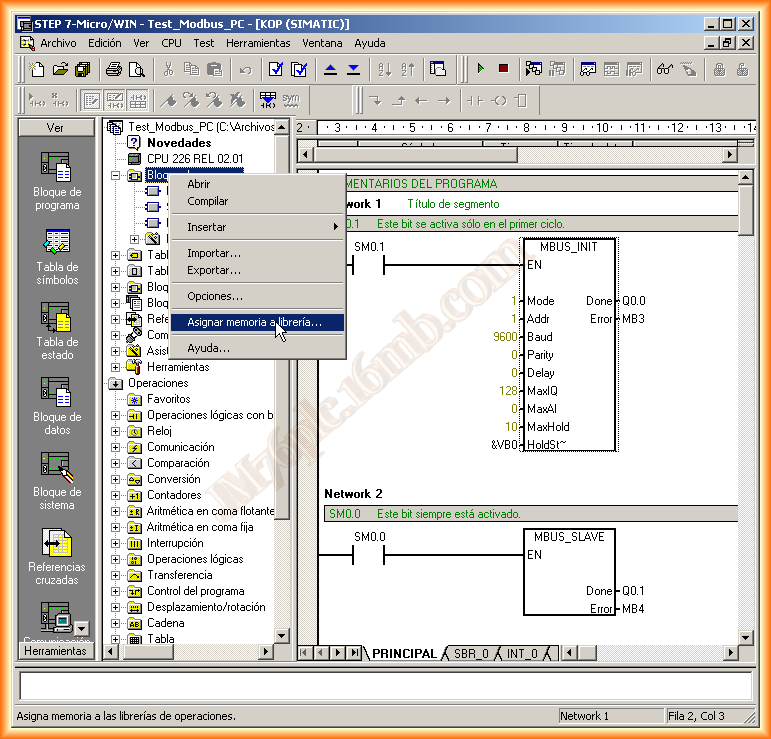
The next thing we need to do is reserve a memory area when using the Modbus functions, for this we go to Program Blocks, right-click -> Assign memory to library
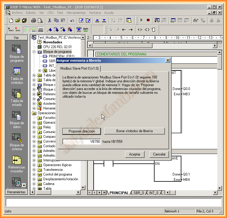
A pop-up window appears and it is advisable to Propose address if we do not have well controlled the memory bytes we have used in our program.
And with this, we can compile and load the program to the CPU, once loaded we close Microwin, to start its verification.
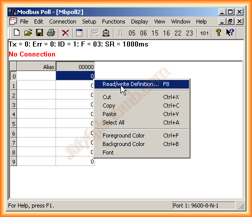
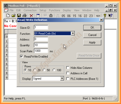
We run Modbus Poll, we have connected the cable from the RS232 Serial port of the PC to the PLC with the cable (RS232-PPI), by default the following image appears, we right-click to specify the area we want to access, I will use the outputs, as I can observe them physically, if I use the registers I should have done some logic to be able to check it
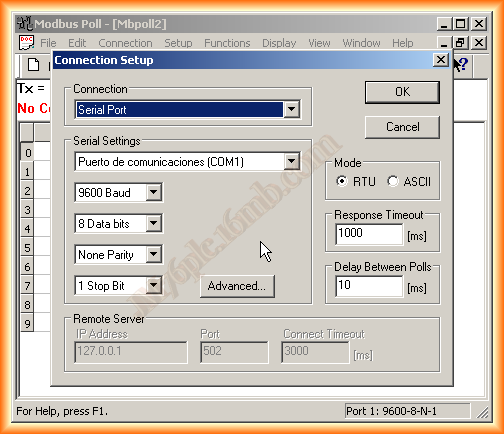
Once defined, we will define the Connection, which will be serial type with COM1 port and its default values, they can be checked by accessing Device Manager -> COM
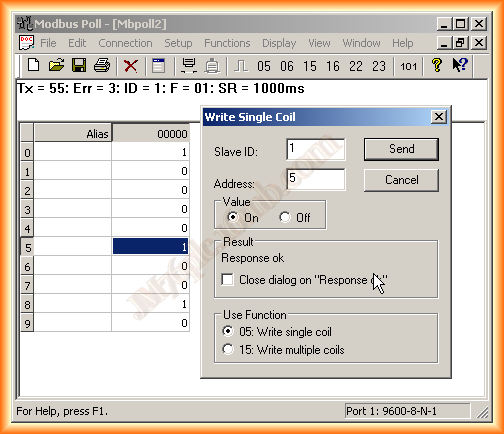
When connected we can observe that the first register 0001 corresponding to output Q0.0 is active, this means that the MBUS_INI function was initialized correctly

Now, if we want to write to the Slave, we double-click on the corresponding register and the following pop-up window opens where we can force the values, I will leave the configuration of it as Master for the next.
December 29, 2012