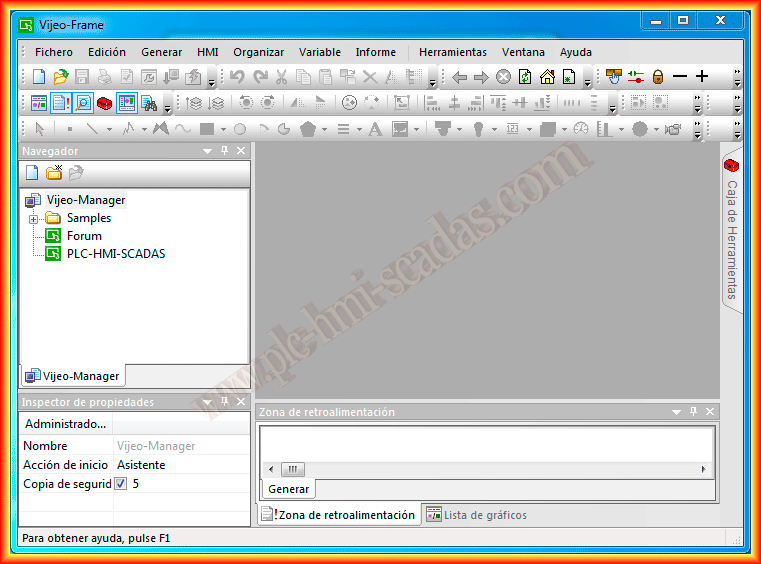
In today's practice, we will see how to configure our Schneider screen to communicate with an S7-1200 PLC. The procedure is very simple; we start Vijeo Designer and create a new project using the wizard.
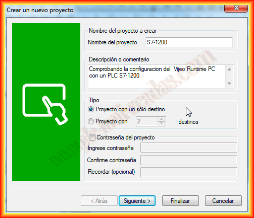
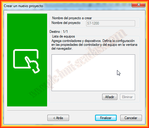
The first thing we do is give a name to our project and specify whether the project will run on a single panel or multiple panels; in this case, it will only run on one.
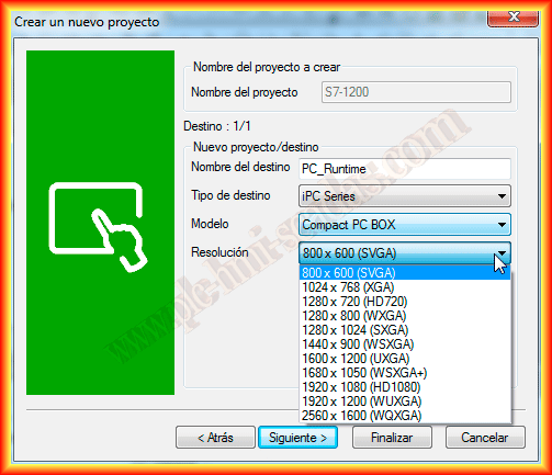
The next step is to specify the name of the HMI with its type and model. I will select an iPC Series to run my project on the PC, although any model is good for simulation.
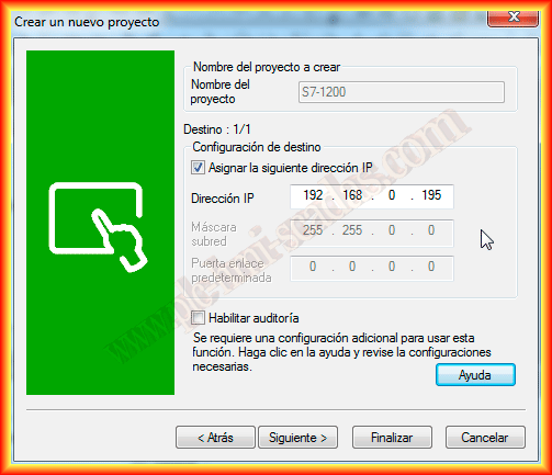
Once the destination, the screen, is defined, we will configure its IP address since we will use the TCP/IP protocol.
The next step is to define the device that will communicate with the screen. This step can be done in the wizard or once in the project; here we will define it in the wizard, so we click add.
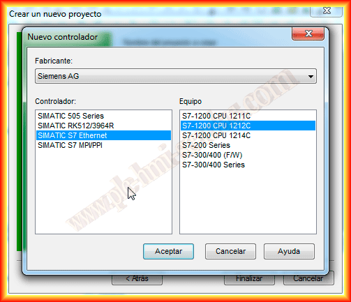
From the available drivers, we select Siemens AG as the manufacturer's brand and the SIMATIC S7 Ethernet driver followed by the device, in this case, an S7-1200 CPU1212C.
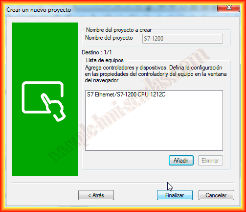
We can now finish the wizard, and our project will be generated.
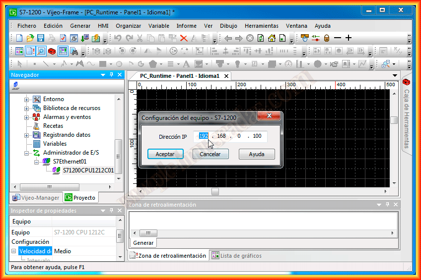
Automatically, the selected driver and our device have been generated in the I/O Manager; the only thing left to configure is the PLC's IP address, in my case, 192.168.0.100. It goes without saying that it must be in the same address range as the HMI Panel. With this, we can now configure the variables that interest us.
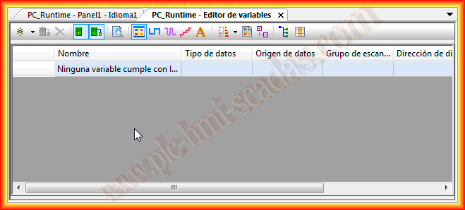
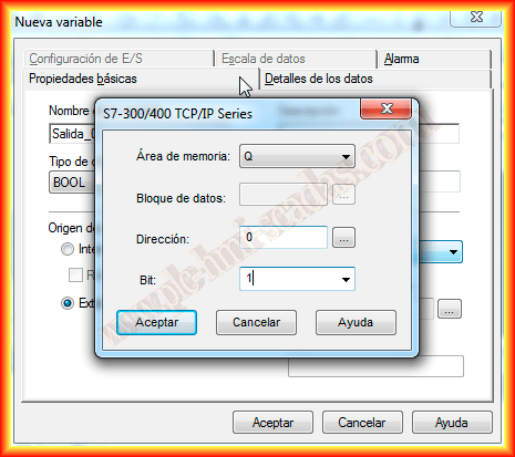
We click on variables, and the following screen opens where we can add the variables we are interested in. To add them, we click on the first icon, and a pop-up window will appear where we select the data type and memory area. Since these are PLC variables, we must select the External Radio Button; if we want to create internal variables, the procedure would be the same, except we would have to select Internal.
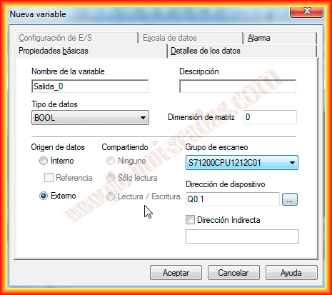
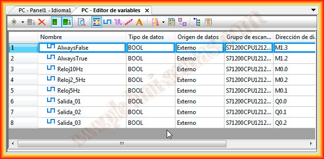
For the example, I used some outputs and the system markers configured in the S7-1200.
Below is the list of variables created for this example.
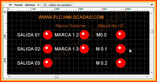
Finally, to test that it works correctly, in Panel1, which is created by default and is configured to be the initial screen, we insert some indicators where each has been associated with its corresponding variable, and we can now start the simulator. When we run it, the compilation will occur, and if there are no errors, it will execute.
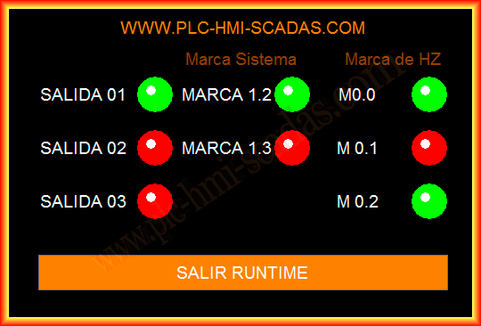
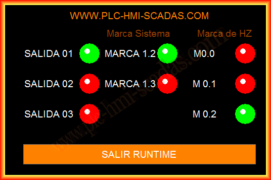
Once the simulator is started or the project has been loaded onto the PC, as was done in the following practice, the Runtime is executed, and the operation is observed correctly as the variables are updated.
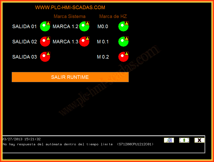
If communication with the PLC has not been initiated or if it has failed, an alarm will be notified as shown in the following image.
March 27, 2013