Vijeo Citect Simulation with Unity
In the following practice, we will see how to configure the Unity simulator to link it with Vijeo Citect and test our SCADA. We start from the basis that we have already created the program in Unity and know how to start its simulator; any doubts can be clarified in the following practice where its realization is explained.
We start Vijeo Citect, and this is the working interface, composed of three applications running in parallel, where each one fulfills its function.
A brief description would be that Citect Explorer is the project manager, where we will create, edit, and delete our projects among its main properties.
The Graphics Builder application is the editor for our screens, and the Citect Project Editor is where we will configure the directories such as Communications, System, Tags, etc.

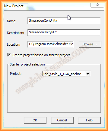
In the project explorer, as we mentioned, we will create our project, right-click -> New Project

A window appears where we configure the name of our project, a description of it, and its directory, which we leave as the default assigned to us. If we leave the checkbox Create project based on starter project selected, we choose the style that interests us from the dropdown list.
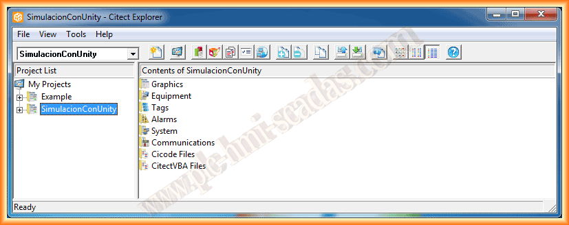
We can now observe that we have created the project and at the same time its organization, subdivided into several directories; we will go directly to the Communications directory.
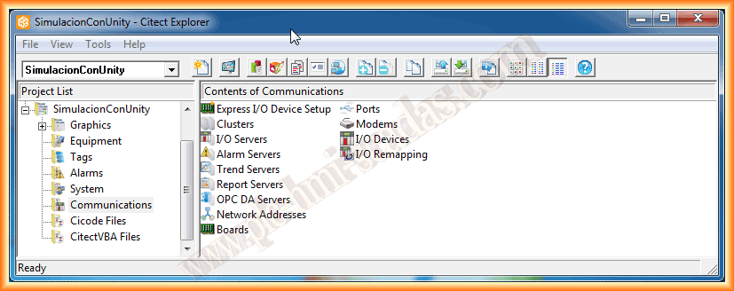
This directory is where we will configure the communication with our PLC (I/O Devices) or, if applicable, with several of them. If you are not familiar with the environment, the easiest way is to configure it using the Express I/O Device Setup Wizard.
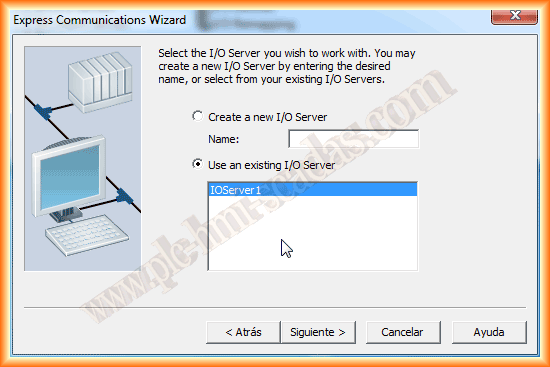
In this first practice, we will use the wizard, and in the next one where I will use a real PLC, we will use the custom configuration. Therefore, we run the wizard; the first step is to create an I/O Server, where we leave the option that the wizard shows us.

Once our server is created, we will create a new device, assigning the name we are interested in. We move to the next image, where we need to specify what type of device it is; we treat the Unity simulator as if it were an External device.


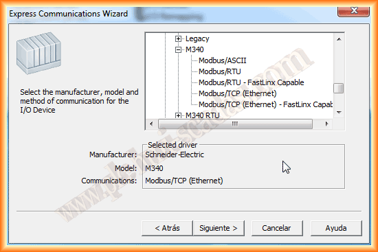
In this next step, we will select the type of device. In our simulator, we have a project created for an M340 where an Ethernet network was configured, so this is the one that interests us.
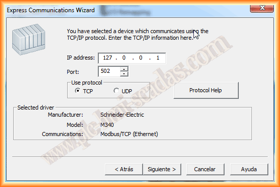
We click next and must specify the IP address of our device. As we have mentioned, the address 127.0.0.1 refers to localhost, which is the address of our simulator.
In the next step, we click next, as we are not going to configure the link of the device with any database or configuration file. With this, we have finished configuring our device.


Having finished configuring the device, we move on to configure the variables that interest us. I have simply created two variables to check the operation; we do this within the tags directory, and they correspond to Variable Tags.

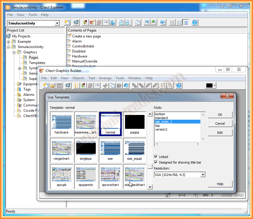
Well, we have configured the device, the variables, and now we will create the screen or user interface. For this, we go to the Graphics directory and within it to Pages, and select Create a new page. The wizard appears to select the type of template that interests us.
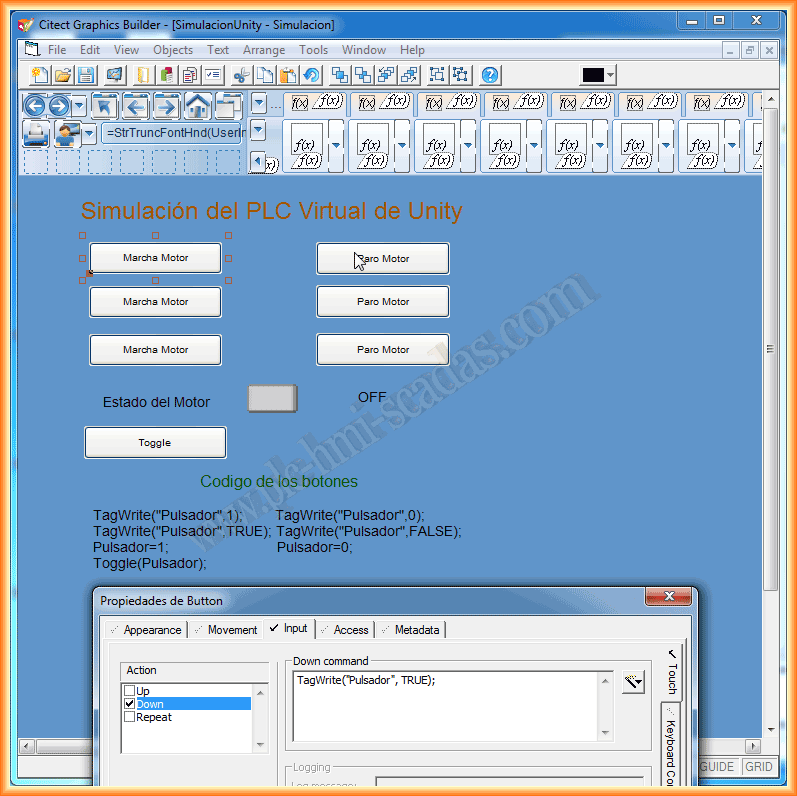
I named it simulation and inserted some buttons with different ways to write in a tag, an object where the color change is configured, as well as a text field.
Finally, before testing our project, in the System directory -> Users -> I will create the user Jose with administrator permissions. These are the necessary steps to compile and run our project.

To check its operation, here is this small demonstration video, and to clarify that it is necessary to have a user logged in with permissions to write to the variables; otherwise, it does not work. As can be observed in the first few seconds of the video, where the button apparently works correctly and changes the text of its variable, but it does not write to the PLC.
June 17, 2013
If you liked it or found it useful, share it...