CP 340 RS232 Configuration
In the following practice, we will configure a CP340 RS232 with the ASCII protocol to connect a Barcode Reader.
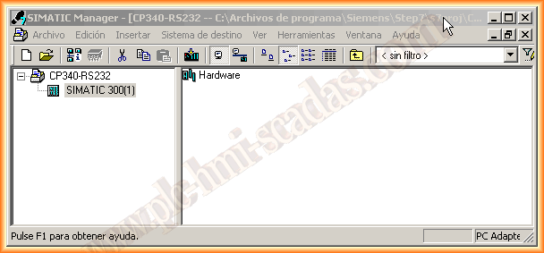
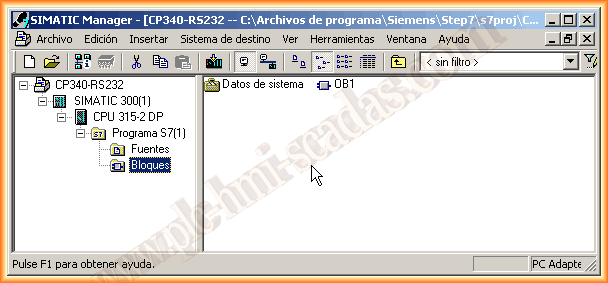
We will create a new project for this, insert a new device of the Simatic 300 type, and the first thing we will configure is the hardware.
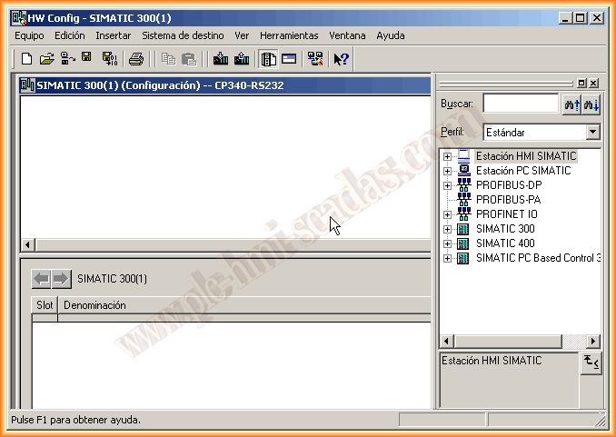
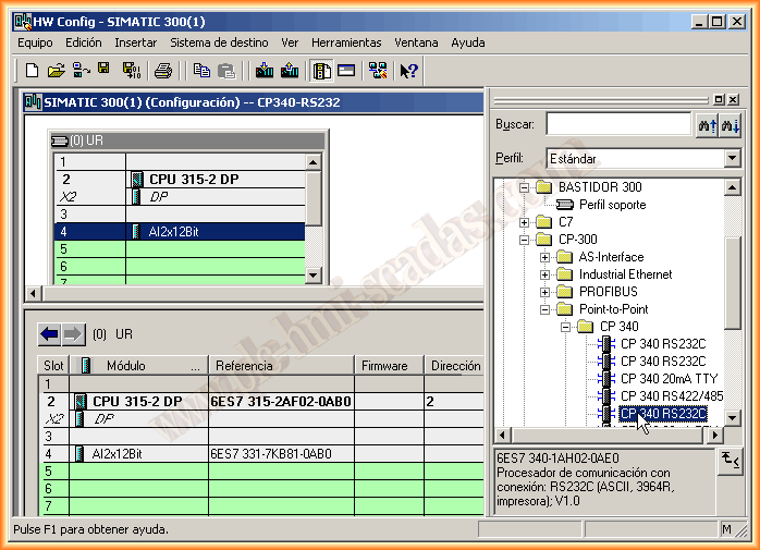
Since it is a new project, all components need to be configured. First, insert the rack and then the other devices until we reach the CP (Communication Processor), which is what we are interested in at this moment. We choose according to our number 6ES7340-1AH02-0A0B.
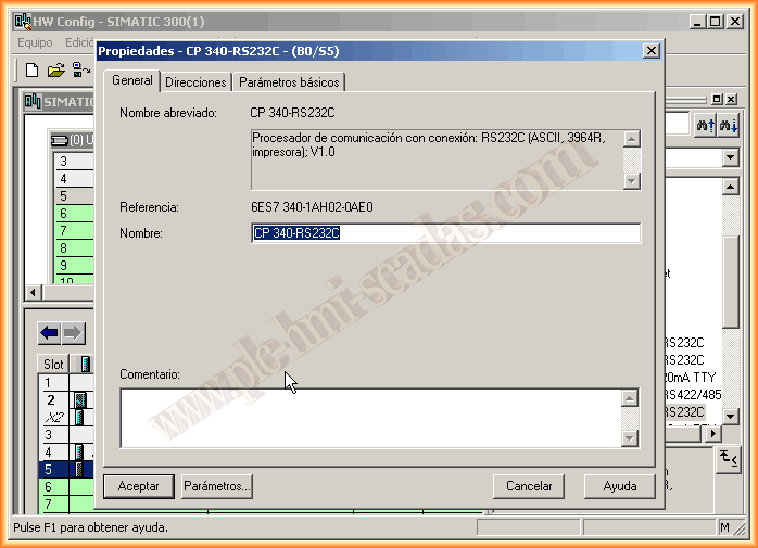
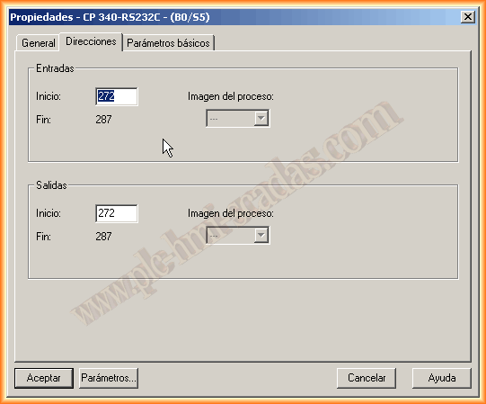
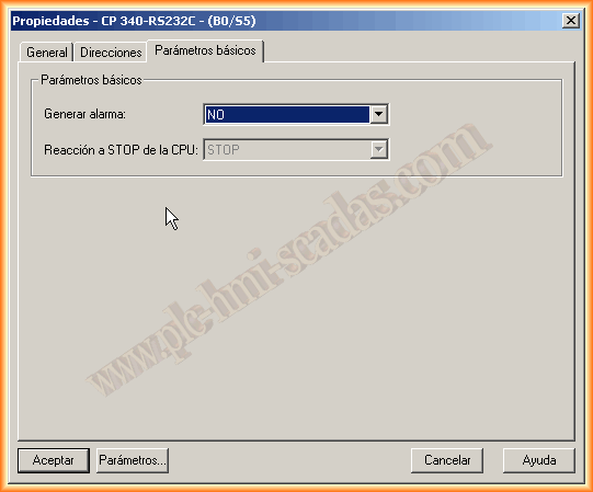
When inserting it into the rack, right-click, device properties, and we have a window with three tabs. The first one is to give it a name; we leave the default name. The second tab is for Addresses, and here we need to stop, as this address is what we will need later when using the Read/Write functions. The next tab is for generating alarms if we are interested. Once these prerequisites are met, we go to the parameters button.
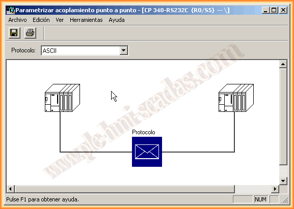
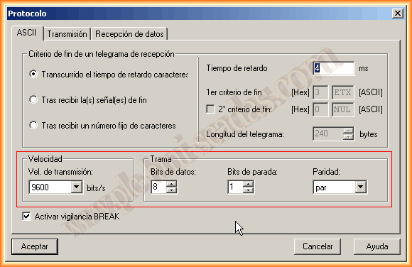
Here we have a small application to parameterize our CP according to our interest. Since I will use it to connect a Barcode Reader, the first thing I will change is the default protocol to ASCII. By double-clicking on the blue protocol box, another configuration window appears where we define the port parameters, speed, data bits, etc. Adjust in accordance with the sending/receiving device.
After finishing the configuration, we click accept, and we can compile and save our hardware. Now we will move on to the software part. For the first test, I will execute my read function in OB1.
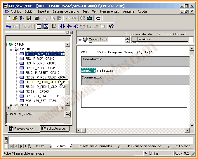
With the CP340/341 comes a CD with the relevant documentation and a library where the functions are ready to be used. In this case, since we want to receive data, we choose FB1, and as can be seen, OLD1 is for older CPUs, as if I were to use FB2 P_RCV, loading the configuration into the CPU would give me an error, since this function works with SFB52, if I remember correctly, and cannot be loaded. That is the reason for using the first one.
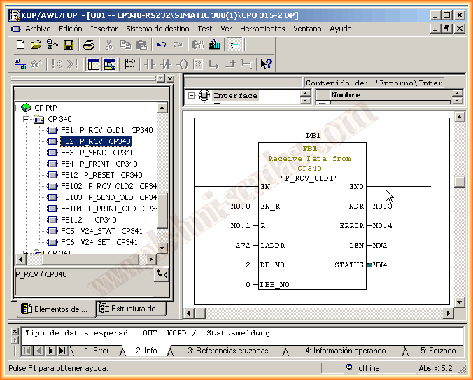
The parameterization of the function is very simple.
EN_R bit for enabling Data reception.
R Reset
LADDR Address that we commented on in the hardware configuration
DB_NO Number of the DB where to store the Data
DBD_NO Number of the Byte from which it will store the data.
NDR Operation performed OK!
ERROR Error bit
LEN Length of processed data
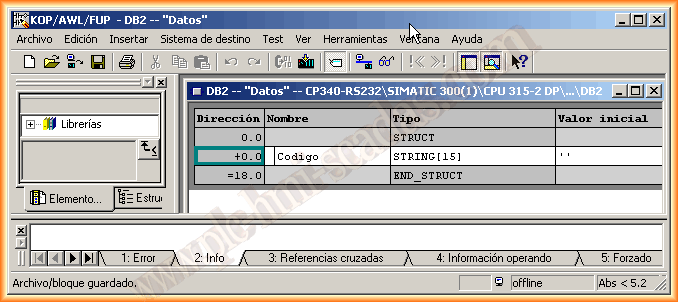
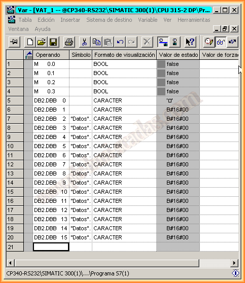
As we have defined in our function that we will store the received data in DB2, we will create it and define where it will be stored. For this, knowing the bytes I will receive, I define a String variable of length 15, as there are 13 characters plus the end and line break.
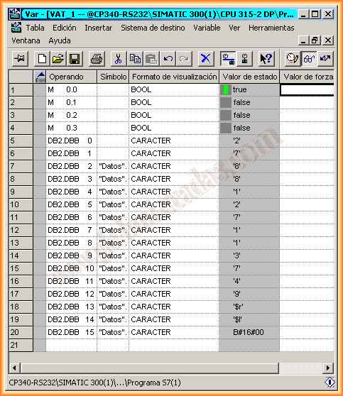
Having compiled and saved everything, we can now load our hardware and software. To make the first tests, I have created a variable table, and when I force M0.0, the CP will be waiting to read the data. Being online, I pass my reader over a barcode, and the operation is correct. From here, adapt according to needs.
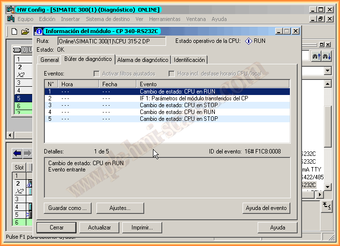
Information from the CP while Online, everything is correct.
June 19, 2013
If you liked it or found the information useful, share it...