Communication between Omron N3BQ-TW01B and S7-200
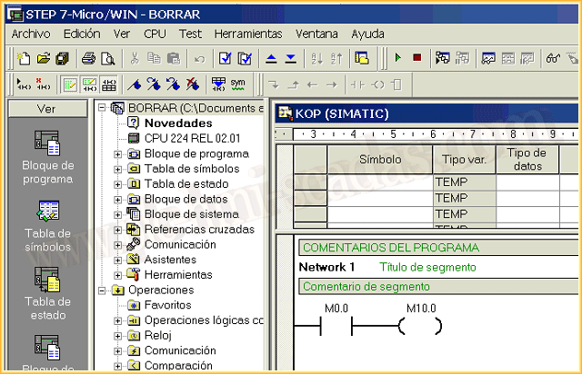
Thanks to Raul and Francisco, we are going to test the operation of an Omron N3BQ-TW01B screen linked with an S7-200 PLC. We will start from the basis that we already have our project created in Microwin, for the example a simple push button, as can be seen in the following image. As we configure the HMI, we will see the parameters we need from the PLC.
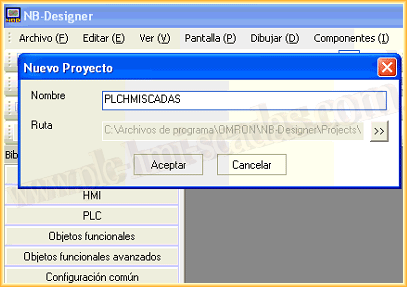
Since there is no tutorial for the NB-Designer, software for programming Omron screens, we will start from scratch. Starting by creating a new project.
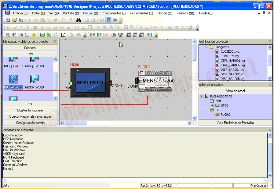
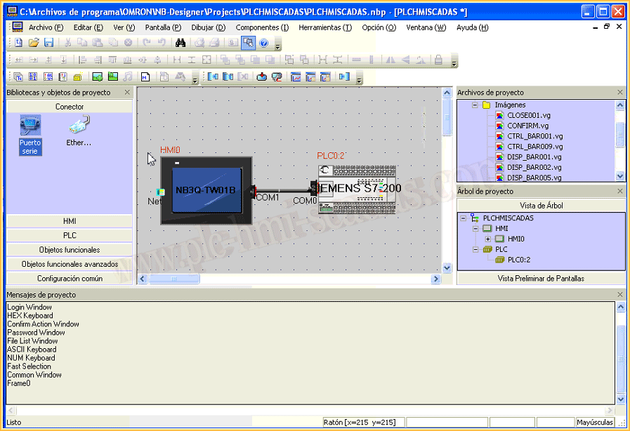
We have already created a new project, and the first thing we will do is navigate in the Object library, and we will select the HMI and the PLC that we have available. To do this, we search in the different directories, select and insert. We have now inserted the HMI and the PLC.
Now we will look at the properties of the HMI. Within the properties, the first option that interests us is the configuration of COM1, since we will communicate through this port and the parameters are as follows. We also observe that if we navigate in the Microwin project, in communication ports we have the parameters corresponding to the speed.
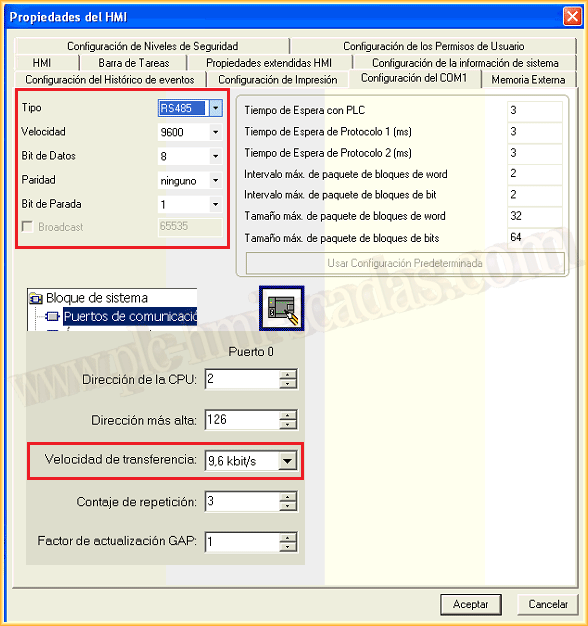
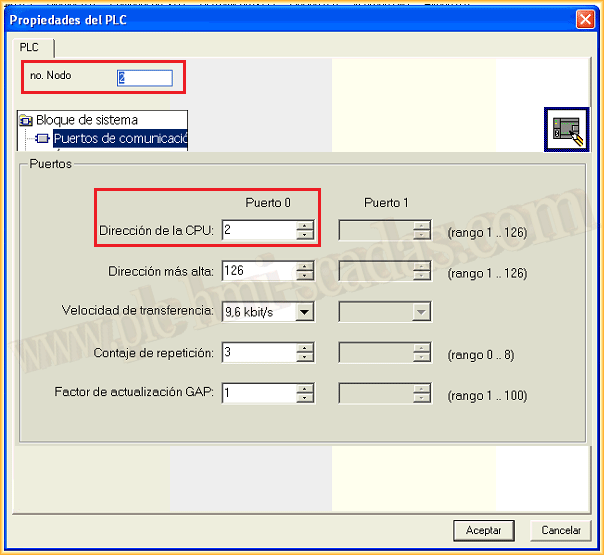
We have already seen the basic properties of the HMI, now we will look at the properties of the PLC, where we only need to specify the node number. In Microwin, we obtain this information in System Block --> Communication Ports.
Once we have configured the properties of both devices, we need to create the link between them. To do this, we navigate to the directory Connector --> Serial Port, and link the two devices.
The next step is to create a screen to test the communication. To perform this test, we will insert two objects, one of the type Bit Lamp and another of the type Bit Switch, as can be seen in the following image.
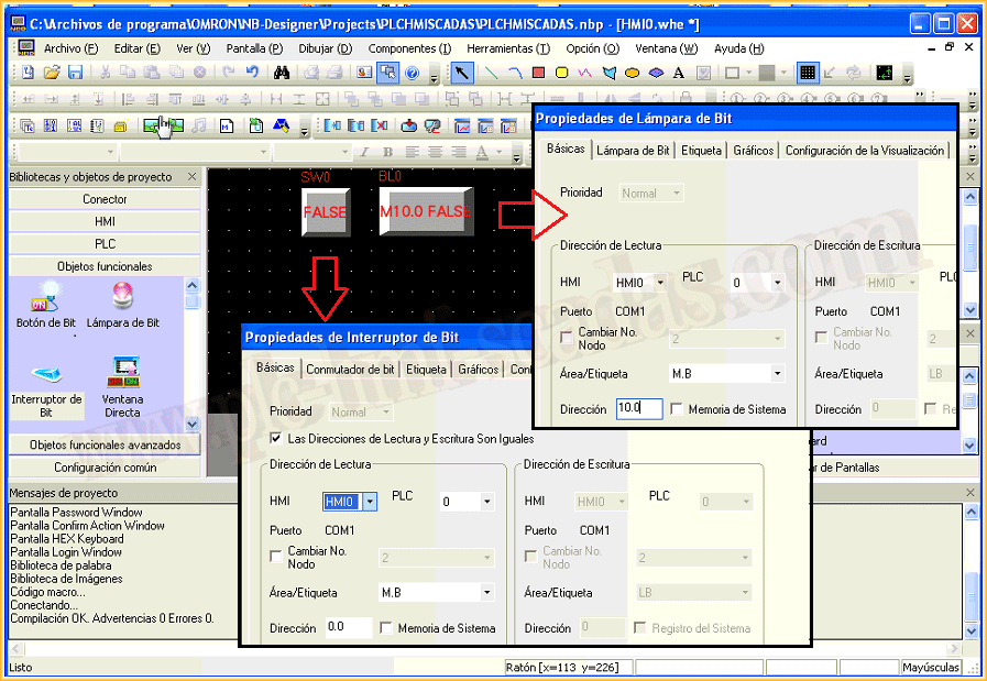
Once the objects are inserted, and we have adjusted their properties, such as colors, texts, etc...
We navigate in the toolbar to Tools and Compile all. At the bottom of the image, the results of the compilation are observed.
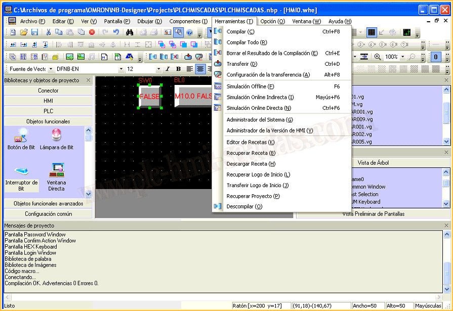
If the compilation has been successful, the first test we are going to perform is a Direct Online Simulation, where we will test our HMI directly with the PLC. To carry out this test, the PLC has the PPI cable connected and is connected to the PC where we are developing our HMI.
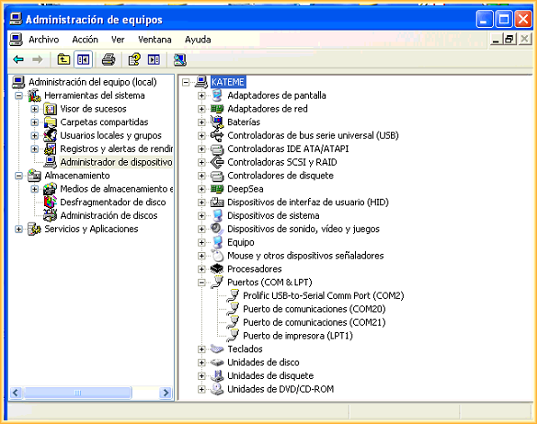
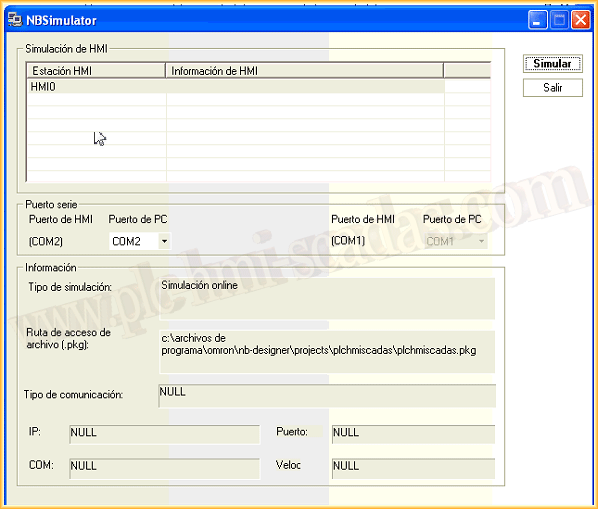
When clicking on Direct Online Simulation, this is the screen that appears, where we adapt the COM port according to our PC, and confirm with Simulate.
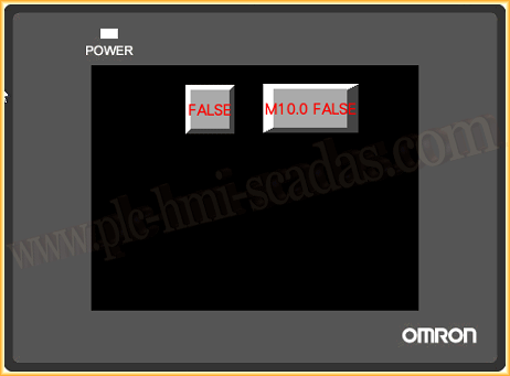
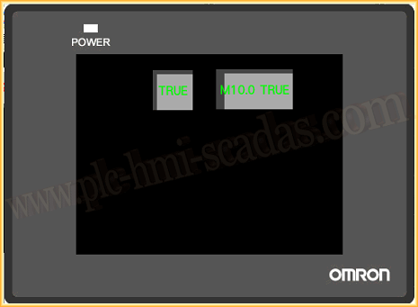
We can now click on the button and observe its operation. The communication is correct and we can now test our entire application.
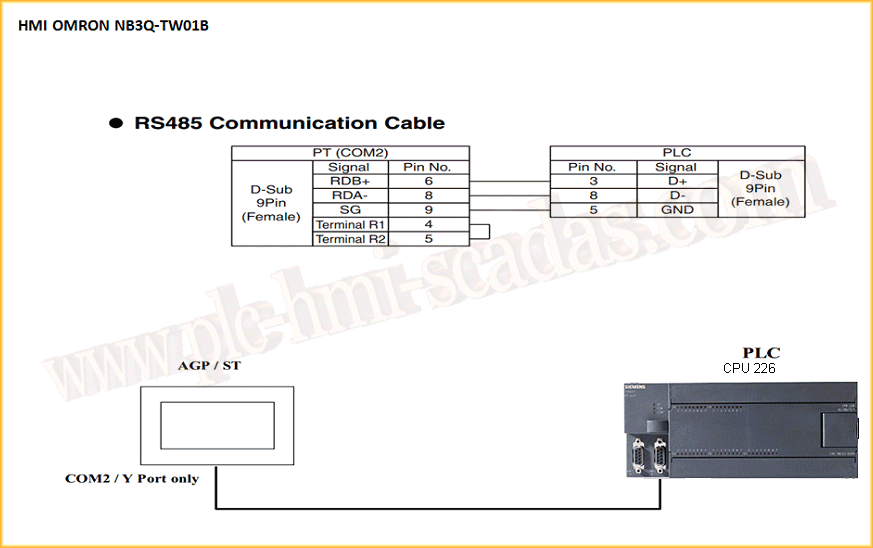
Once this test has been carried out and our application debugged, we can download the application to the HMI. The communication cable between the PLC and HMI is as follows:
August 26, 2017
"Gratitude in silence serves no one." Gladys Bronwyn Stern