With this practice, we will see if we can help the people who have written to me regarding the OP3. Well, the first thing we need to keep in mind is that the programming of this device is done with ProTool, which is the predecessor of WinCC Flexible 2004.
The OP3 is a line display, which is very limited in functionalities, and it was usually seen in installations for making parameter changes, such as times, counters, and other operations performed in the PLC.
In my example, the goal will be to change a time and a counter, but it is applicable to other functionalities.
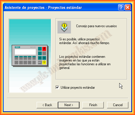
I create a new project and continue with the wizard, as it will help me configure it. First, I select the type of OP/TP/MP followed by the protocol to be used, depending on the type of PLC we have.


Since the target is an S7-200, I have configured that protocol and in parameters, we adjust the PLC address, which by default is usually 2, but if we are not sure, we communicate with the PLC and parameterize the port address as well as the speed. As a profile, we select PPI if it is going to be a point-to-point link, although it is also possible to configure it as MPI, Profibus.
The interface of the OP is IF 1A since it only has one communication port. If this is the first time we are using ProTool, it is interesting to select the checkbox to use the standard project, as it will create some images that will help us.

We finish the wizard, and the following project is created. We can already see that we have some images with some useful functions, and in controls, we have our S7-200 configured.


Assuming that we have not selected the creation of a standard project and we are going to create it from scratch, we will see some simple steps. First of all, we insert a new image. It should be noted that each image has a maximum of 20 lines. Each time we are on a line, we have the soft keys enabled. Our OP has 5 keys, as can be seen, and it is there that we will configure the functions that interest us.

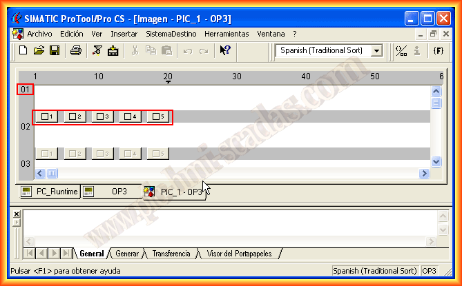
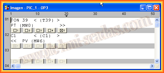
As we have said, we are interested in visualizing the value of a timer T39 and at the same time changing its time. We will apply the same to a counter C1.
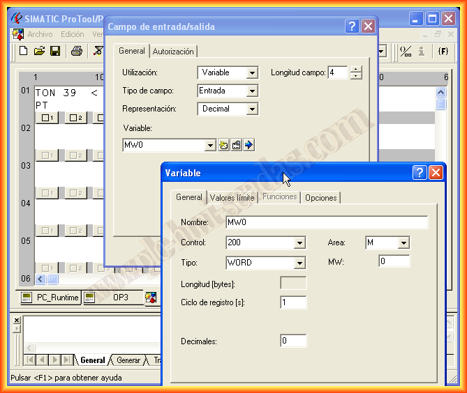
With the cursor over line 01, we can write the text that interests us. Since we are primarily interested in knowing the value of the Timer, we insert an input/output field, but we will configure it as an output since it will be for visualization. As we do not have created variables, we create a new variable, select the data type as well as the memory area, give it the name we are interested in, and that's it.
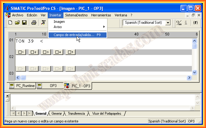

Just as we did to visualize the value, we are now going to create another input/output field, but this time it will be for input and will refer to the memory area MW where we can change the value of the timer. We create the variable and assign it.
We have already configured the first line of our first image. Now, we want to change to the second line. For this, we will use key 5, where by selecting it, we will apply a function.
The function we are interested in is Image branching, and the parameters passed will be the input number, which will be the line we want.


We had configured the first line; in the same way, we configure the subsequent lines and all the images we need.
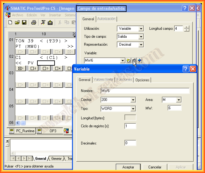
In variables, we can see that as we have been creating new variables, they are reflected. If we need to modify them, we can do so in their properties.

To check that it works correctly, I have created some segments in a microwin program for the 200, where some of them can be observed here.
The simulation with ProTool is also available, but not for all types of OP; this one does not support simulation. We could only see its operation by linking it directly with the PLC, but to test it, I have created another project in ProTool where the destination is the PC Runtime. Here you can see this example.
.png)
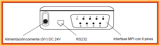
Assuming that we have already completed all the OP configuration, we just need to transfer it. The necessary steps and interface are as follows, but first of all, we need to know the ports of our OP3.
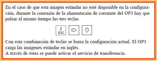
The steps to make the transfer are as follows: in case a program has already been loaded and we want to perform a new transfer, we apply the key combination.

If we want to make the communication cable between the OP3 and the PC with the serial port, this is the pinout that needs to be done:

And the cable between the OP3 and our PLC is as follows. All this information is extracted from the OP3 manual, which you can download directly from Siemens or from the following link.

May 1, 2013
If you liked or found the information useful, share it...