Factory Talk View Server "Site Edition Network"
The following practice aims to create a network project with Factory Talk View SE, which is based on Client-Server architecture. This means that it is essential to have a network of computers where all must belong to the same Workgroup or, if we are talking about a Server operating system, within the same domain. For the development of the example, I will use a workgroup, where all the computers are on the same network, I have enabled file sharing, and the user must log in to access the operating system.

The first thing we are going to do is prepare the machine that will be the Server, for this we will use the tools installed in the following directory Factory Talk Tools.
Start->Rockwell Softwares->Factory Talk Tools
The first application we are going to use is the Factory Talk Directory Configuration Wizard, as its name indicates, it is a wizard for configuring the directory.

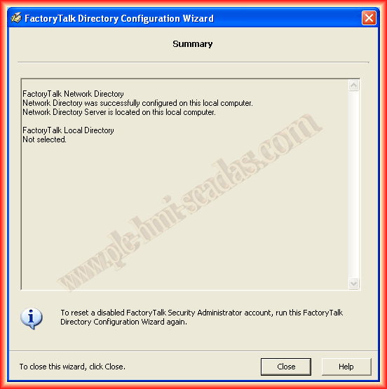
Following the wizard, I select the checkbox to configure the directory in the network.
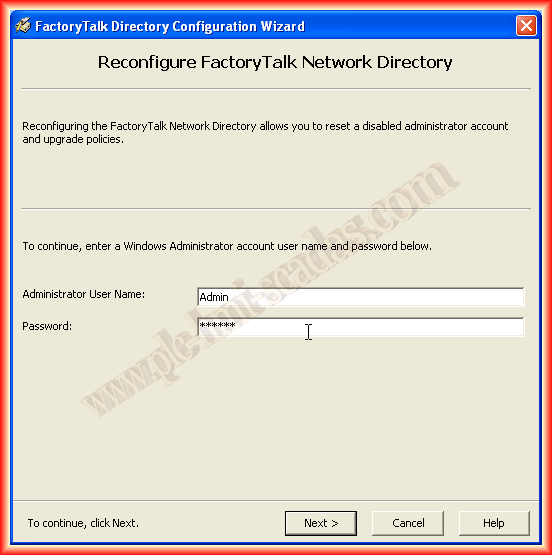
To make changes, it is necessary to have logged in as Administrator, so we use the user with the corresponding password, and with this, it is already defined.
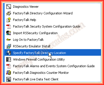
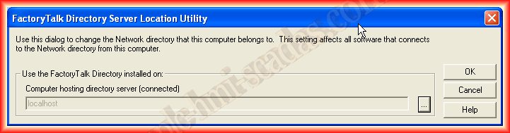
Another tool that will be useful later when configuring the client is the one shown on the screen, in the case of the server, the directory is created on localhost, the machine itself.
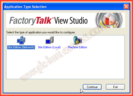
Once the previous steps are completed, we are ready for the creation of our project, we run FTView and will clarify some doubts, the difference between Factory Talk View SE and ME lies in the fact that the former is for creating Rockwell's Scada, this is the successor to RSView32, however, the ME version is for configuring the Panel Views, the HMIs. Once this is clarified, we will create a Site Edition (Network) project.
We assign a name that interests us to the application, add a description, and select the language.

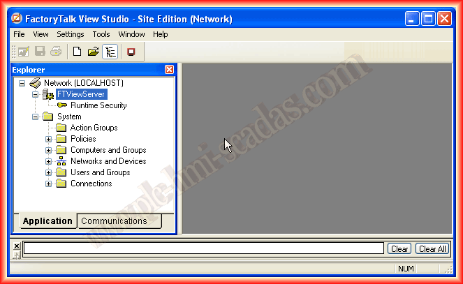
When creating a new project, the interface is as follows, where the first difference compared to a local application is that Network (Localhost) appears and the tree appears as observed.
The first thing I am going to do is add a new area, this will help us assuming that we are going to have several clients, and each client will have its displays, its images; with the help of areas, we can organize our project. The example could be an area for production, an area for storage, an area for the laboratory, etc...

Within the created area, we are going to add a new server of the HMI Server type. This would be equivalent to a local application; each area or subarea must have at most one HMI Server, and it will be where we will later configure to connect the Client.


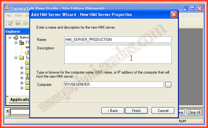
When adding a new HMI Server, the following wizard appears with several options; we select according to our interest, whether it is creating a new HMI Server, copying an existing one, importing a project from RSView32, FTView SE, or FTView ME, and finally attaching an existing one. For this example, I will create a new one, the name I have assigned is HMI_SERVER_PRODUCTION, and the computer where it will be created is the Server.

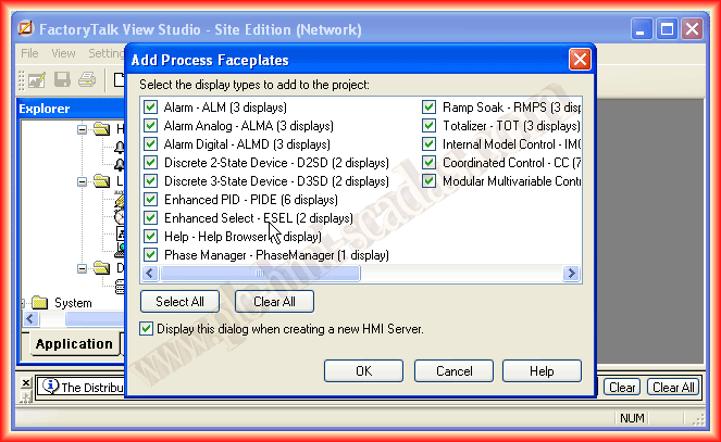
Finally, we click on finish, and our project is created. A window appears in case we want to select any faceplates, although we can use them at any time.
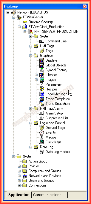
As can be seen in the explorer, our HMI Server hangs from the created area; in the same way, we could create new areas with new HMI Servers, as shown in the next image:

As general information, the directory where the projects are created is as follows, where we can see ours; it is necessary to know it because we will need it when configuring the client(s).

In this practice, we will not go into details on how to configure the different objects, although what we have done subsequently in Factory Talk View ME for the panels is applicable; you can review what is here.
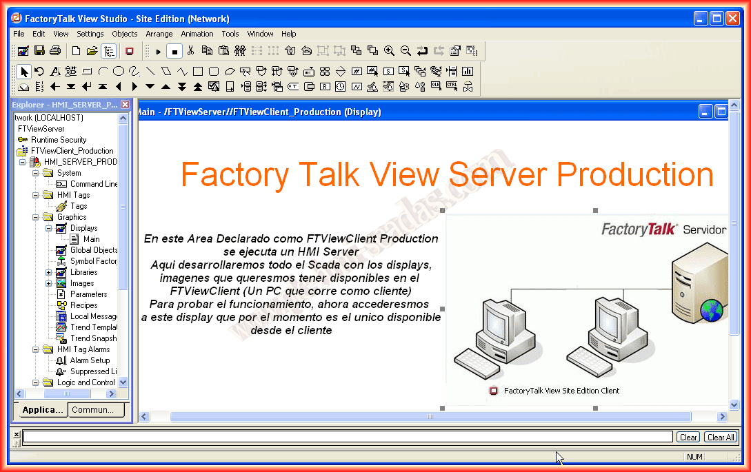
Continuing with our objective, I have created an image as can be seen, but here all the necessary configuration would need to be done.
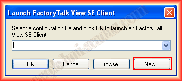
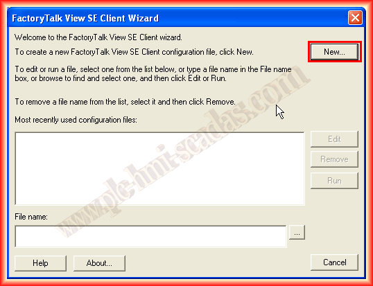
Assuming we have finished our project, we will proceed to run a Client on the Server; for this, we run the FactoryTalk View SE Client. Since we have not yet created our *.cli file, we will create a new one, and the wizard for its creation automatically appears, and we click on New again.
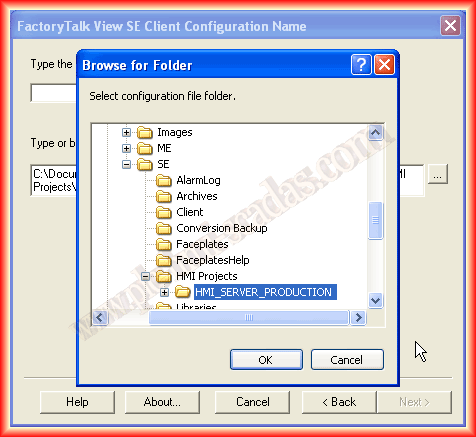
The first thing it asks us is the name we are going to assign to our file and the path where the project is located. Since this client is being executed on the Server, we look for the directory we mentioned earlier and select the created HMI Server project.

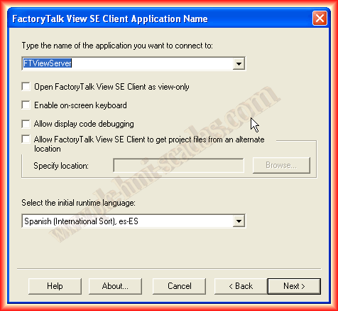
The next step is to specify whether it is a network or local project; in our case, it is Network. We click next and select the project name; in addition, we can select the options that interest us, such as a client for viewing only, enabling the on-screen keyboard, and others...

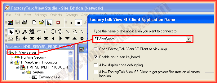
The next image is helpful, as this was the name given when creating a new network project, but in the directory we have seen, what is saved is the configuration of the HMI Server project.
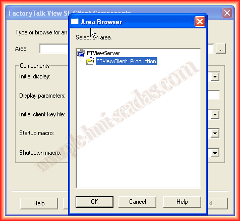
The next step is to specify the Area where the HMI Server is located; we have already mentioned that there can only be one HMI Server per area or subarea.
And we select the other options, at least the initial image, since we have not taken any action in the other options.

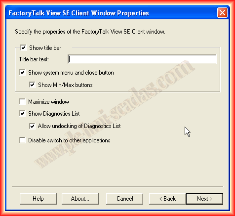
Continuing with the wizard, we select according to our interest; by default, it appears as it is, which is perfect for testing, it should be resizable and minimizable, show the system menu, and display the diagnostic list. Finally, we save the configuration, and upon clicking finish, the client is executed.

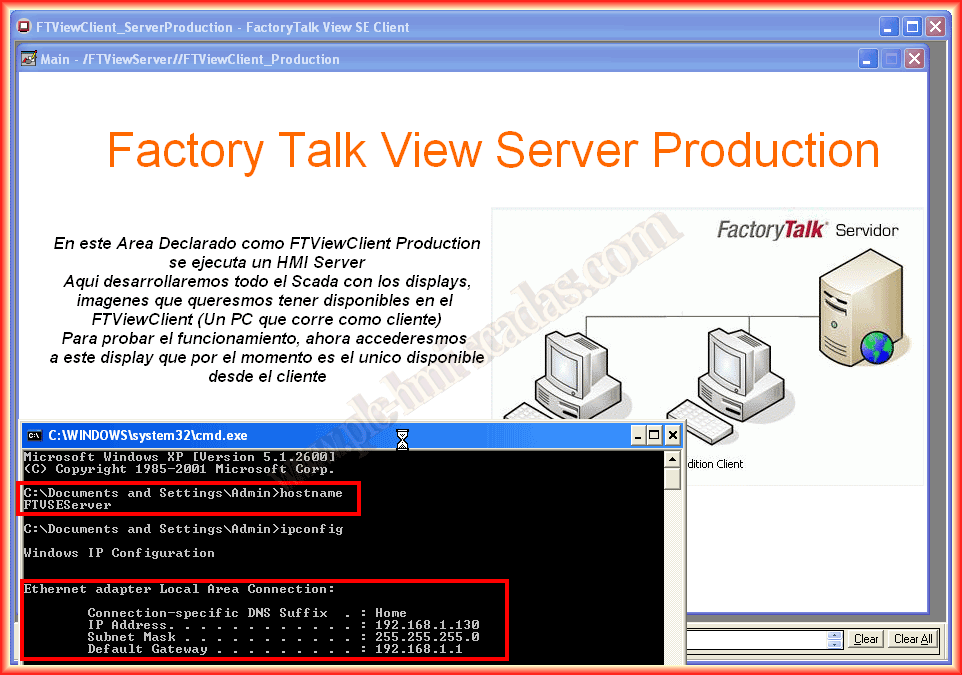
The Client has started, and here we can observe our project. As can be seen, this client is running on the Server. Now, to run the client on another machine, the steps are practically the same, but for any doubts, here are the steps to follow.
May 3, 2013
If you liked or found the information useful, share it...