PanelBuilder32 Configuration Communications Setup
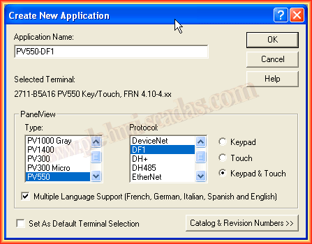
In the following practice, we will revisit the PanelBuilder32 software and an old Panel View 550 to see how to configure some of its features. Today we will see how to configure the connection with the Controller using the different protocols supported by this Panel View. We create a new project, selecting the type of PanelView, protocol, and model.
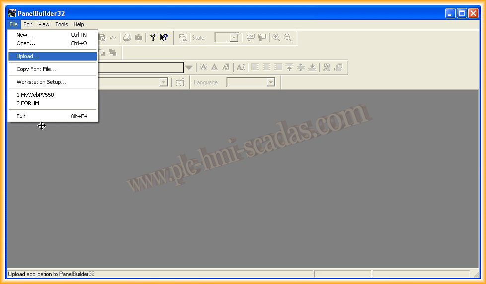
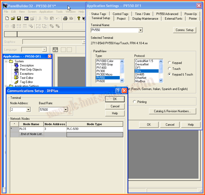
This is the interface that the software shows when creating a new application; today we will focus on Communications Setup, the communication configuration with our Controller.
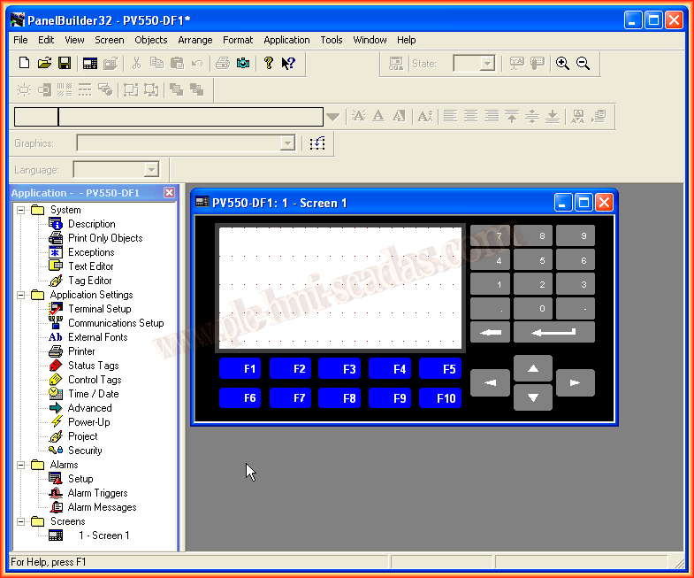
To access the communication configuration, we can either go from Terminal Setup, where we will have all the configuration tabs, or in Communications Setup, which automatically opens Terminal Setup and in turn Comms Setup.
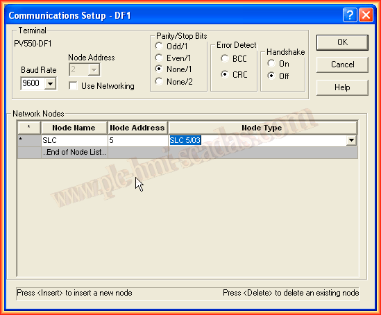
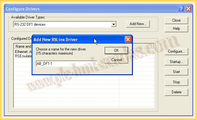
In this first case, we will assume a Serial communication with the DF1 protocol. The first thing we need to do is insert a new Node (Right-click) as shown in the image.
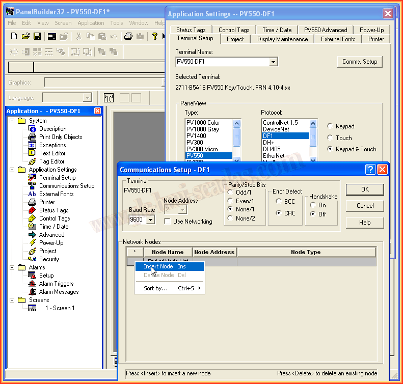
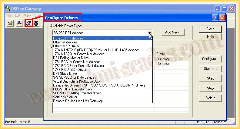
We assign a name of our choice to the Node, followed by the address. If we do not know it, it can be obtained from RSLinx, and in Node Type, we will select the type of Controller with which we want to establish communication. By default, the PanelView has address 2; if we want to change it, we check the Use Networking checkbox to edit it. With this, the connection would be configured.
In the next example, we will assume that we are going to connect to a PLC5/40 under the ControlNet protocol, and we will assume that this is our network, where each node has its address.

In Node Name, we assign the name of our choice, followed by the address that our Controller has on the Network. Finally, we select Type Node and adjust it according to our Controller; for this example, Allen-Bradley PLC.
In this case, we will assume that we have a DeviceNet network, as shown below.
For this type of communication, we assign the address of the PanelView and the network speed, and in I/O Scanner, we specify the number of words (0 to 64) to send/receive to the scanner in each I/O message. The number of words must be identical to what was configured in the Master.
In a DH+ network, we assign the desired name in Node Name, the address of our controller on the Network, and the type in Node Type. Our PanelView in this case has address 2, and the network speed is 57600.
The next example belongs to a DH485 Network; the PanelView has address 2, and the network speed is configured to 19200. We will communicate with an SLC5/03 Node Type that has address 3 on the Network. The name we assigned is SLC3.
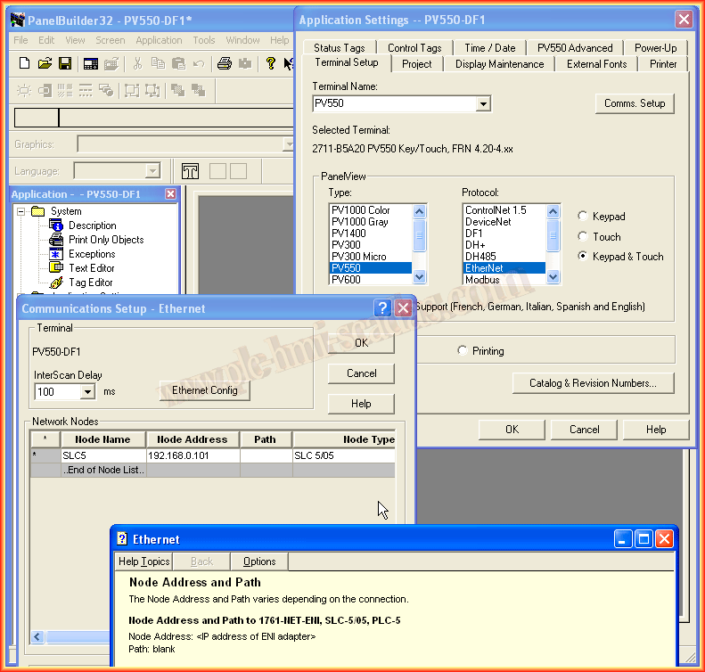
Now we will assume an Ethernet/IP network as follows:
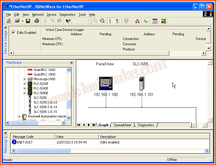
In this case, the first thing we need to do is assign the IP address to our PanelView. We do this from Ethernet Config, or if using DHCP/Boot, we leave its corresponding checkbox selected.
With the address assigned to the PanelView, we insert a new node and assign it the IP address of our Controller, in this case, an SLC5/05, which are the only Processors that include an Ethernet port. For this type of Controller, we will leave Path blank as it is.
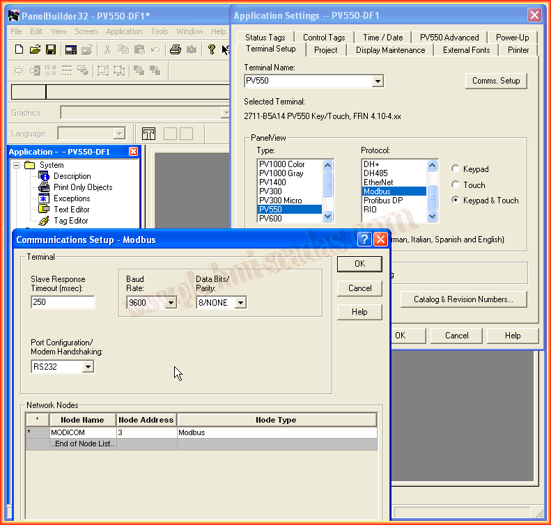
Now we will assume a Modbus RTU network, where we will communicate with a Modicon that has address 3 and will operate on a network with a speed of 9600 as can be seen.
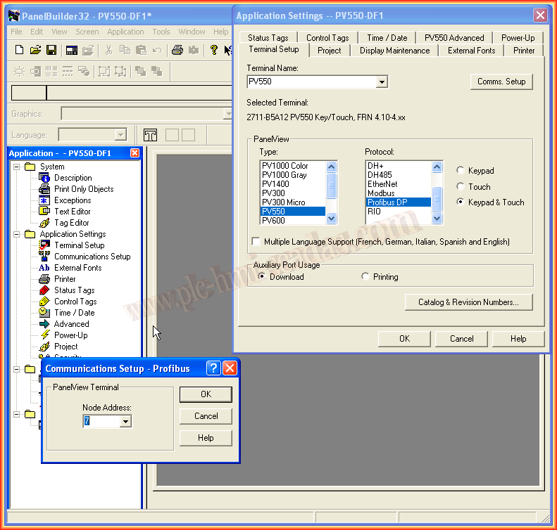
In a Profibus DP communication, we only need to assign the address of the Panel View in the Profinet Network.
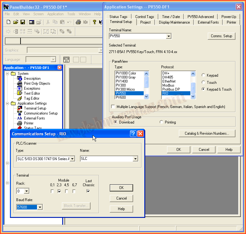
And finally, in a communication with the RIO protocol, we need to assign the type of Scanner in our Controller, Rack, and module.
July 23, 2013